
Volume
0.16 – 0.32 – 0.5 – 0.75Design pressure (bar)
100 – 140 – 210 – 250 – 280Membrane material
NBR – ECOAccumulator material
CARBON STEELCode example:
| TYPE | GAS CONNEC. | NOMINAL VOLUME | SEP. ELEMENT MATERIAL | BODY MATERIAL | FLUID CONNECTION | CERTIF. | DESIGN PRESSURE |
|---|---|---|---|---|---|---|---|
| WAL | M28x1,5 | 0,75 | 1 | O | B4 | A | 210 |
WAL · 2 · 0,75 · 1 · O · B4 · A · 210
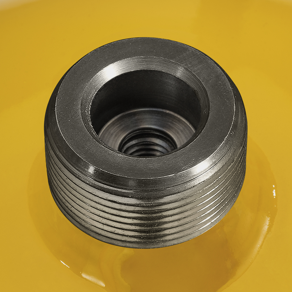
Description: Electron-beam welded accumulator WAL M28x1,5 – Vol. 0,75 L – NBR – CARB. STEEL – F. 1/2” GAS (DIN3852-2 Form X large) – Mod. 210 bar
Principle of Operation
One of the main tasks of hydraulic accumulators is to take up a certain amount of fluid under pressure from a hydraulic system, and then return it all, or part of it, to the system when required.
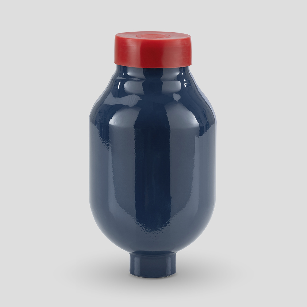
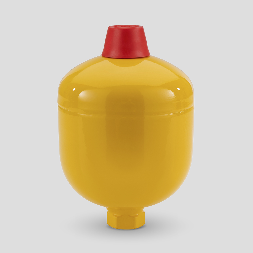
Since they are pressure vessels, they must be sized for the maximum working (over) pressure, taking into account the acceptance standards valid in the country of installation. In most hydraulic systems, accumulators with a separating element between the fluid and gas side are used. Type WA maintenance-free diaphragm accumulators consist of two shells made of high-strength steel and electron-beam welded together.
The U-shaped diaphragm separates the gas side from the fluid side. A special back plate closes the bore of the fluid side when the accumulator is preloaded to prevent extrusion of the diaphragm. The gas valve is available in the classica lM28x1.5 version with an Allen locking screw and metal-to-rubber sealing washer (for pre-charging, the DP100 pre-charging and control equipment must be used).
The fluid connection is available in the standard threaded connections shown in the table. Compared to other types, these accumulators have a high energy efficiency, as they have a higher energy density (energy content / mass); this characteristic is due to the almost spherical shape of the accumulator body.
Type WA accumulators can be installed in any position.
Type WA maintenance-free membrane accumulators cannot be repaired.
Tecnical Characteristics
- Construction Electron-beam welded, not reparaible
- construction
- High-strength alloy steel body
- Standard painting
- Anticorrosive primer
- Gas side connection M28x1,5
- Fluid side connection
- Separating element material
Applications
- Energy reserve in systems with intermittent operation due to reduced pump power.
- Energy reserve for emergency cases, such as in the event of pump-motor unit failure or power failure.
- Compensation of losses due to leakage.
- Pressure compensator (balancing).
- Vibration dampening in the event of periodic oscillations.
- Volume compensation in the event of pressure and temperature variations.
- Hydraulic suspension spring on vehicles.
- Shock absorption in the event of mechanical impact.
Certifications
All hydraulic accumulators are pressure vessels and are subject to the national norms and to the norms valid in the country of installation.
WA-type accumulators are built according to the European Directive PED 2014/68/EU.
In the table Technical Data the relevant category related to the use with non dangerous fluids (group 2) is stated. For the use with dangerous fluids (group 1) please contact SAIP. For other countries, applications, norms, SAIP has to be contacted.
Safety Equipment
Hydropneumatic accumulators must be protected against operation outside the permissible limits according to the Pressure Equipment Directive 2014/68/UE on pressure equipment.
In order to not exceed the maximum operating pressure,
SAIP recommends the use of a safety block.
