
Volume (L)
4 – 6 – 10 – 20 – 25 – 35 – 42 – 55Design pressure (bar)
140 – 250 – 360Membrane material
NBR – NBR-40°- EPDM- H-NBR – ECO – FKM(VITON)Accumulator material
ACC. CARB. – AISI316L – SAFCode Example:
| TYPE | GAS CONNECTON | NOMINAL VOLUME | SEP. ELEMENT MATERIAL | MAT. BODY | FLUID CONNECTION | CERTIF. | FLANGE SHANK |
|---|---|---|---|---|---|---|---|
| SI | 1U | 10 | 10 | O | F | B | CSO3G |
SI . 1U . 10 . 10 . O . F. B . CSO3E
Description:
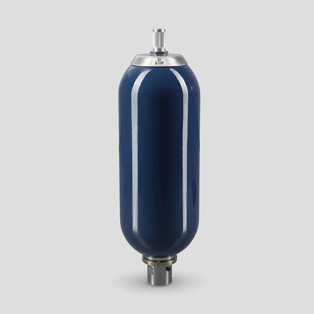
Accumulator /Pulsation damper type SI – Valv. 5/8” UNF – Stem 7/8” UNF – Vol. 10 L – FKM – CARB. STEEL. – 2” SAE 3000 Flange Shank
Principle of Operation
One of the main tasks of accumulators is to take a certain amount of pressurised fluid from a hydraulic system, and then return it, in whole or in part, to the system when required.
Bladder accumulators work like a hydraulic spring: the gas (nitrogen), contained in the rubber bladder, is separated from the fluid in the system. When the hydraulic system pressure becomes greater than the pre-charge pressure of the nitrogen, the fluid enters the accumulator and is stored as potential energy inside, due to the compressibility of the gas. When the system fluid pressure decreases, the nitrogen pressure expands and returns the stored fluid to the system.
Operating pressures adapted to the maximum allowable pressure allow a pressurised fluid to be accumulated, stored and recovered at any time. As pressure vessels, they must be sized for the maximum
operating (over) pressure, taking into account the acceptance standards valid in the country of installation.
Bladder-type SI accumulators consist of a seamless cylindrical body made of high-strength steel. The rubber bladder is mounted inside the body. Through the gas valve, the bladder is filled with nitrogen up to the expected precharge pressure P0 (special equipment must be used for precharge).
Tecnical Characteristics
- Repairable construction
- Seamless high-strength
- Steel body painted
- Gas side connection 5/8” UNF.
- Fluid-side connection
- Separator element material
Applications
- Energy reserve in systems with intermittent
operation due to reduced pump power. - Energy reserve for emergency cases, such as in the event of pump-motor unit failure or power failure.
- Compensation of losses due to leakage.
- Pressure compensator (balancing).
- Vibration dampening in the event of periodic oscillations.
- Volume compensation in the event of pressure and temperature variations.
- Hydraulic suspension spring on vehicles.
- Shock absorption in the event of mechanical impact.
- Pulsation damping
Certifications
All hydraulic accumulators are pressure vessels and are subject to the national regulations and directives in force in the country of installation.
The accumulators type SI are manufactured in accordance with the European Directive PED 2014/68/EU, reference standards EN 14359:2017 and EN13445-3:2021; they are also in accordance with ASME VIII Div. 1 – Appendix 22, with U-STAMP.
The Technical Data table shows the category for use
with non-hazardous fluids (group 2).
Safety Equipment
Notice:
Hydropneumatic accumulators must be protected against operation outside the permissible limits according to the Pressure Equipment Directive 2014/68/EU. In order not to exceed the maximum operating pressure, SAIP recommends the use of a safety block.


